| Welcome To Evlithium Best Store For Lithium Iron Phosphate (LiFePO4) Battery |
 |

EVLithium BMS
Programmable EVLithium EBS-BMS Functions & Settings
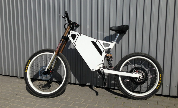
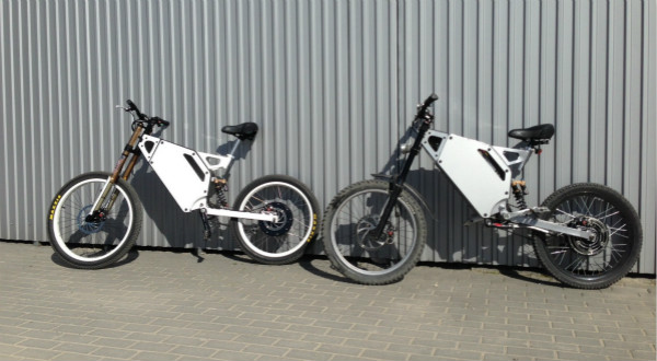
The programmable E-Bike Smart BMS (EBS-BMS) applies to superpower E-bike or E-motor which are equipped with a li-ion battery packs using less than 24 cells in series. (≤24s and any number of parallel cells).
The EBSBMS uses Linear Technologies battery management chip LTC6803,and microprocessor to achieve high accuracy, stability and safety.

Features
・ supports 4-24s Li-ion battery pack,max 100V
・ controls max.30A charging current, no limit discharging current
・ controls E-bike electric lock (e-lock for short below), control E-bike throttle
・ balances passively max 23 cells simultaneously at max. 200mA bleeding current
・ monitors max. 4 external temperatures and 1 internal temperature
・ monitors charging current with built-in sensor (+-50A) and discharging current with external sensor (+-200A/400A)
・ supports 2.8inch LCD display
The BMS does:
・ monitor all cell voltages V_cell
・ monitor the battery pack current I_bat
・ monitor battery pack and BMS temperature T_pack(4 channels) and T_sys (1 channel)
・ SOC automatically learning and calculation
depending on the parameter settings the BMS will:
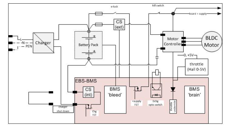
・ detect and handle alarming situations (OV, UV, OC, UT, OT) by disconnecting e-lock/throttle or charger
・ detect and handle charge and discharge limits of the battery pack
・ detect unbalanced cells and control bleeding
|
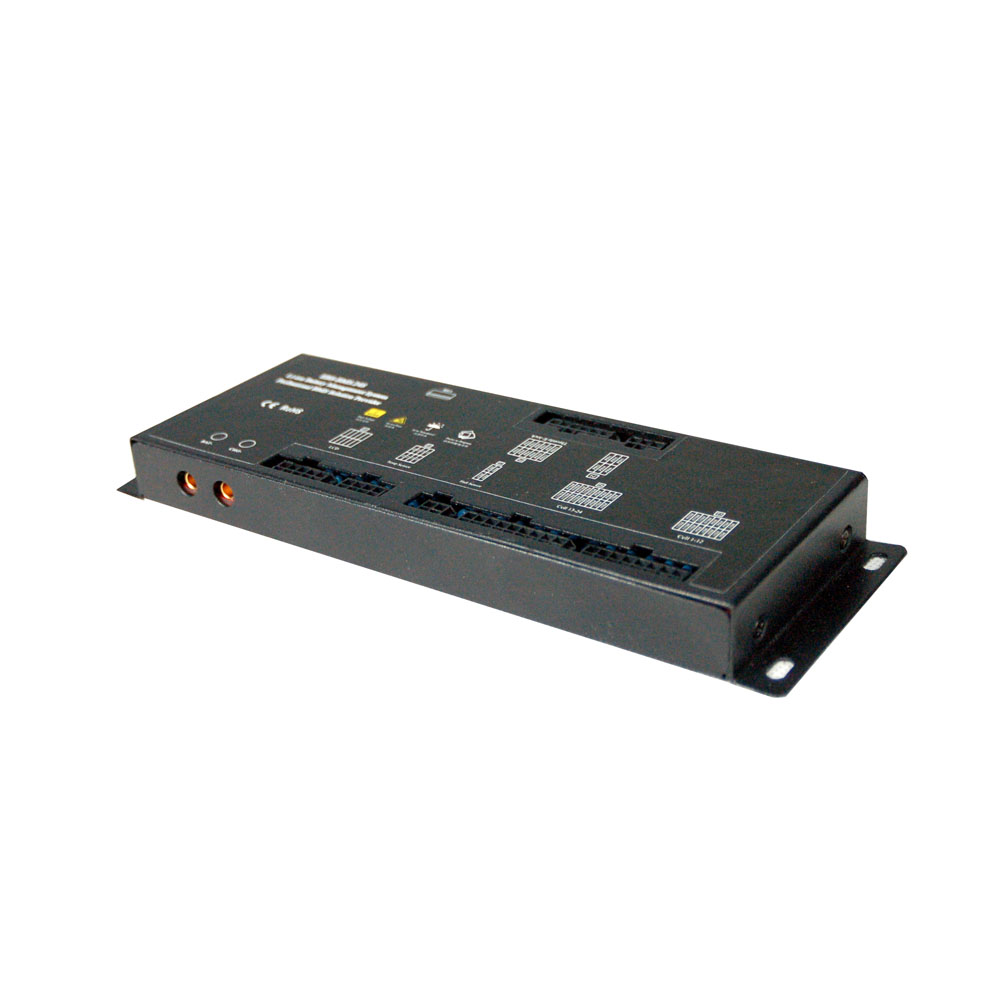
EVLithium EBS-BMS (Smart BMS for E-bike Throttle Control) |
|
|
battery pack configuration |
4-24s |
|
DCHG current handling capacity |
nominal: no limit (Choose appropriate CS) |
|
CHG current handling capacity |
max continuous: 30A |
|
supply voltage |
10V-100V for 4-24S |
|
passive cell balancing |
200mA,,max 23 cells simultaneously |
|
SOC (calculated) |
accuracy ±2.5% over one cycle |
|
V_cell measurement |
resolution 5mV, accuracy ±0.2% |
|
current measurement |
Internal CS for charging ±50A ±2.0% |
|
external CS for discharging, ±100 - 600A ±2.0% |
|
|
supply current |
20mA normal(e-lock is on) 0mA standby(e-lock is off) |
|
communication |
TTL-USB for PC and LCD |
|
throttle control |
PWM 5kHz, for clamping Hall element throttle signals 1-4V |
|
auxiliary control |
Cool and heat control signal (opto coupled open collector) |
|
States (For charging) |
CHG FET |
|
V_cell>= CHG_Limit |
OFF |
|
V_cell<=CHG_Recover |
ON |
|
Over T_pack |
OFF |
|
Over T_pack Recover |
ON |
|
Over T_sys |
Keep original state |
|
Under T_pack |
OFF |
|
Under T_pack Recover |
ON |
|
Over Charging I_bat |
OFF and Recover after 3 min |
|
Plug on charger when e-lock is off |
V_cell>= CHG_Recover OFF V_cell<= CHG_Recover On,e-lock on |
supply current
20mA norma (e-lock is on)
0mA standby (e-lock is off)
communication
TTL-USD for PC and LCD
throttle control
PWM 5kHz, for clamping Hall element throttle signals 1-4V
auxiliary control
Cool and heat control signal (opto coupled open collector)
|
States (For discharging) |
E-lock and Throttle |
|
V_cell<= DCHG_Limit |
OFF |
|
V_cell>=DCHG_Recover |
ON |
|
Over T_pack |
OFF |
|
Over T_pack Recover |
ON |
|
Over T_sys |
Keep original state |
|
Under T_pack |
OFF |
|
Under T_pack Recover |
ON |
|
Over Discharging I_bat |
OFF and Recover after 5 min |
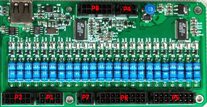
Opto-coupler switch
Opto-coupler switch is in P8.
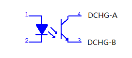
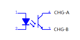
Discharging on, DCHG opto LED ON.
Current will be permitted between DCHG-A&DCHG-B.
Charging on.CHG opto LED ON.
Current will be permitted between CHG-A&CHG-B.
PWM
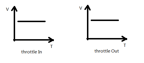
PWM State
When battery is in lower power state,signal of throttle controller will be changed by BMS.
When battery is in normal state,voltage of throttle in and throttle out are the same.
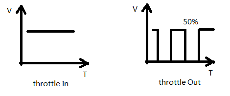
When battery is in lower power state,output signal will be 50% duty ratio modulated by
PWM signal in order to let output power reduce to 50%.Recuperation Current
BMS has two current sensor.One is the internal CS(current sensor) to monitor charging current.
The other is the external CS to monitor discharging current.Besides that,external CS can also
monitor recuperation current.This kind of CS is the two-way current sensor.When e-bike is downhill
or braking,recuperation current will be monitored and BMS will calculate this part of current to SOC.
(In general,customers use 100BT or 200BT external SC,so if recuperation current is too small,CS
can not monitor and BMS will not be calculate it to SOC.)
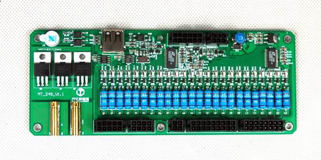
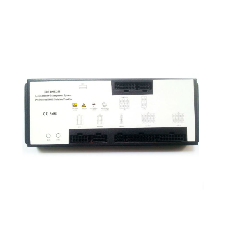
8. BAT-, 2. CHG-, 3. LCD, 4.Temperature sensor (4 channels), 5. External Temperature sensor
9. Cell 13-24 monitoring/bleeding (No.2 JST 18pin), 7. Cell 1-12 monitoring/bleeding (No.1 JST 16pin),
10. Buzzer, 9. TTL-USB, 10 Throttle/E-lock connector, 11. firmware update
|
P5 |
|
|
P5-1 |
B- |
|
P5-2 |
B- |
|
P5-3 |
B1+ |
|
P5-4 |
B2+ |
|
P5-5 |
B3+ |
|
P5-6 |
B4+ |
|
P5-7 |
B5+ |
|
P5-8 |
B6+ |
|
P5-9 |
B7+ |
|
P5-10 |
B8+ |
|
P5-11 |
B9+ |
|
P5-12 |
B10+ |
|
P5-13 |
B11+ |
|
P5-14 |
B12+ |
|
P5-15 |
B12+ |
|
P5-16 |
NC |
|
P6 |
|
|
P6-1 |
B13- |
|
P6-2 |
B13- |
|
P6-3 |
B13+ |
|
P6-4 |
B14+ |
|
P6-5 |
B15+ |
|
P6-6 |
B16+ |
|
P6-7 |
B17+ |
|
P6-8 |
B18+ |
|
P6-9 |
B19+ |
|
P6-10 |
B20+ |
|
P6-11 |
B21+ |
|
P6-12 |
B22+ |
|
P6-13 |
B23+ |
|
P6-14 |
B+ |
|
P6-15 |
B+ |
|
P6-16 |
NC |
|
P6-17 |
NC |
|
P6-18 |
NC |
|
P7 |
|
|
P7-1 |
+5V |
|
P7-2 |
HALL |
|
P7-3 |
GND |
|
P7-4 |
NC |
|
P1 |
|
|
P1-1 |
NTC1+ |
|
P1-2 |
NTC1- |
|
P1-3 |
NTC2+ |
|
P1-4 |
NTC2- |
|
P1-5 |
NTC3+ |
|
P1-6 |
NTC3- |
|
P1-7 |
NTC4+ |
|
P1-8 |
NTC4- |
|
P2 |
|
|
P2-1 |
+5V |
|
P2-2 |
GND |
|
P2-3 |
LCD_DATA |
|
P2-4 |
LCD_CLK |
|
P2-5 |
LCD_CS |
|
P2-6 |
LCD_RES |
|
P2-7 |
LCD_BL+ |
|
P2-8 |
LCD_BL- |
|
P2-9 |
+3.3V |
|
P2-10 |
BUTTON |
|
P4 |
|
|
P4-1 |
NC |
|
P4-2 |
NC |
|
P4-3 |
NC |
|
P4-4 |
NC |
|
P4-5 |
NC |
|
P4-6 |
NC |
|
P8 |
|
|
P8-1 |
ISO_VCC |
|
P8-2 |
Throttle In |
|
P8-3 |
Throttle Out |
|
P8-4 |
NC |
|
P8-5 |
ISO_GND |
|
P8-6 |
NC |
|
P8-7 |
DCHG-A |
|
P8-8 |
DCHG-B |
|
P8-9 |
CHG-A |
|
P8-10 |
CHG-B |
|
P8-11 |
LOCK_IN |
|
P8-12 |
LOCK_OUT |
|
P3 |
USB Connector to PC |
|
N5 |
B- |
|
N6 |
CHG- |
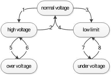
Table 2 Description of states (see Figure 2)
|
State |
Description |
|
normal voltage |
No OV, UV event; Permit charge, discharge if no other protection events |
|
high voltage |
Prohibit charging; Permit discharge if no other protection events; if discharge current exists, that is discharge current < discharge state threshold, turn on CHG FET |
|
low voltage |
Prohibit discharge, When pre-charge function is enabled, if V_cell < UV threshold, permit pre-charge but prohibit charge; if V_cell ≥ UV threshold, permit pre charge and charge if no other protection events; When pre-charge function is not enabled, prohibit precharge but permit charge if no other protection events; If charge current exists, that is charge current > charge state threshold, turn on discharge MOSFET |
|
over voltage |
same as high voltage; issue alarm |
|
under voltage |
same as low voltage; issue alarm |
Table 3 Description of states (see Figure 2)
|
Transition |
Initial State |
Final State |
Condition |
|
1 |
normal voltage |
high voltage |
HV event occurs (V_cell ≥ HV threshold & delay timer expires) |
|
2 |
high voltage |
normal voltage |
HV event clears (V_cell < HV release value & delay timer expires) |
|
3 |
normal voltage |
low voltage |
LV event occurs (V_cell ≤ LV threshold & delay timer expires) |
|
4 |
low voltage |
normal voltage |
UV event clears (V_cell > LV release value & delay timer expires) |
|
5 |
high voltage |
over voltage |
OV event occurs (V_cell ≥ OV threshold & delay timer expires) |
|
6 |
over voltage |
high voltage |
OV event clears (V_cell < OV release value & delay timer expires) |
|
7 |
low voltage |
under voltage |
UV event occurs (V_cell ≤ UV threshold & delay timer expires) |
|
8 |
under voltage |
low voltage |
UV event clears (V_cell > UV release value & delay timer expires) |


|
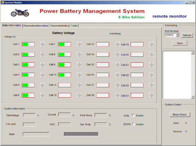
Name |
description |
limits [unit] |
remarks |
|
Cell 1-24 |
display the real time cell voltages as well as OV/UV status and balancing status |
+5.399 [V] |
the dots to the right turn red when bleeding of this cell is on. Bleeding starts with a delay of approx. 5min |
|
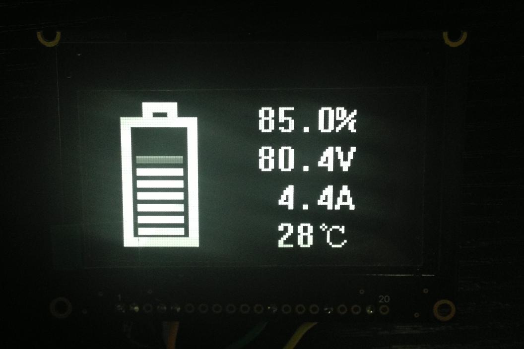
Total Voltage |
displays actual battery pack voltage |
+130.0 [V] |
|
|
Current |
displays actual battery pack current |
+300.0[A] |
|
|
Pack Temp |
displays actual battery pack temperature |
+125.0 [°C] -30.0 [°C] |
external temp sensor |
|
Sys Temp |
displays actual battery pack temperature |
+125.0 [°C] -30.0 [°C] |
internal temp sensor |
|
CHG Enable |
indicates charging mode |
true / false |
|
|
DCHG Enable |
indicates discharging mode |
true / false |
|
|
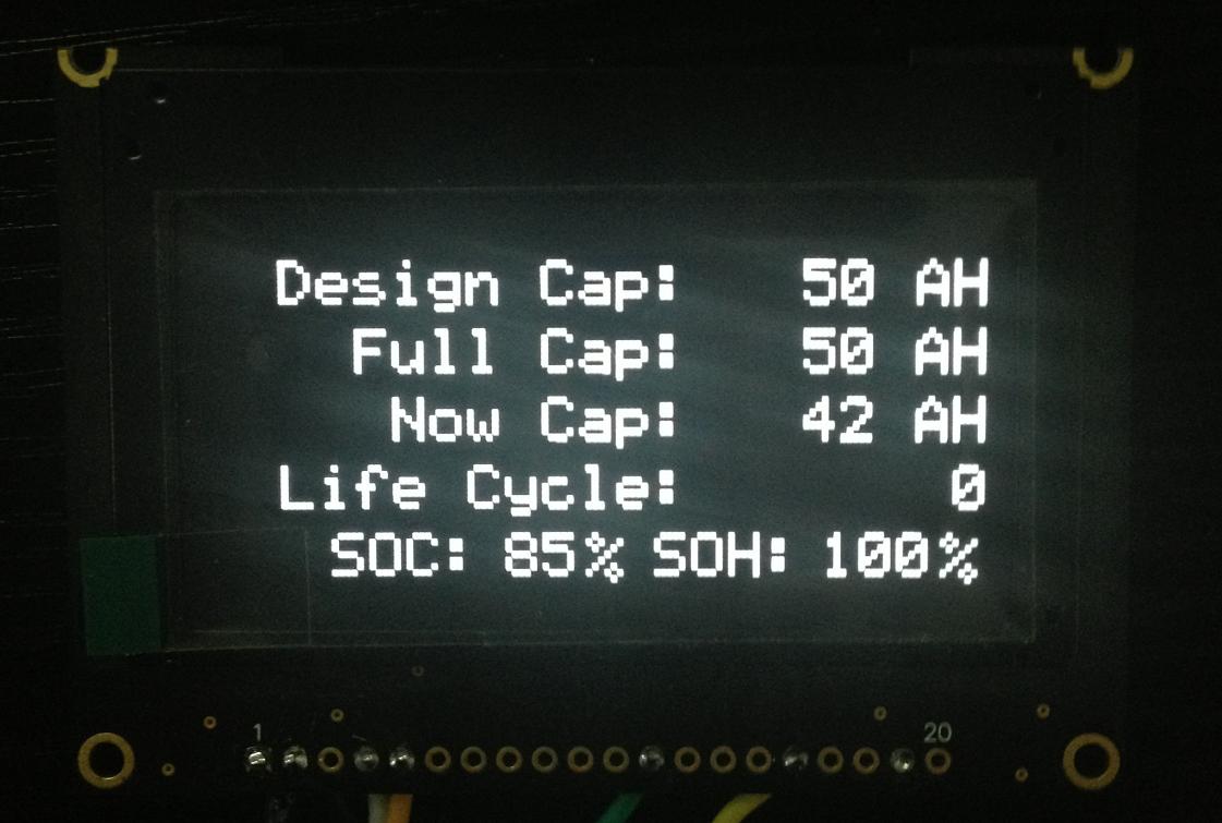
Life cycle |
displays the number of charge/discharge cycles |
000 |
|
|
SOC |
displays the State of Charge of the battery pack |
||
|
State |
displays the system's state |
Discharging/Charging/ (Standby/OV/OC/OT/UV/Short/) |
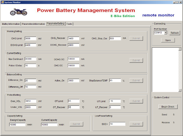
Parameter Settings
|
Name |
description |
range [unit] |
action if threshold is exceeded |
|
CHG Limit |
sets the maximum cell voltage |
0<V≤5'000 [mV] |
switches off CHG-FET |
|
CHG_Recover |
sets the reset voltage of the 'CHG Limit' state |
0<V≤5'000 [mV] |
switches on CHG-FET when the 'highest' cell returns to the CHG_Recover threshold |
|
CHG_Stop_Cur |
sets minimum charge current |
0<I≤5'000 [mA] |
switches off CHG-FET after xx seconds |
|
DCHG Limit |
sets the minimum cell voltage |
0<V≤5'000 [mV] |
switches off throttle & e-lock |
|
DCHG_Recover |
sets the reset voltage of the 'DCHG Limit' state |
0<V≤5'000 [mV] |
switches on throttle & e-lock |
|
Max_Continue_I |
sets the max discharge current |
0<I≤200'000 [mA] |
|
|
Pulse_I_Delay |
max. duration of pulse current |
1<t≤30 [s] |
|
|
DCHG_OC |
sets the pulse current |
switches off CHG- and throttle & e -lock and triggers OC alarm |
|
|
CHG_OC |
sets the max charging current |
switches off CHG- and throttle & e-lock and triggers OC alarm |
|
|
Difference_On |
sets the max cell voltage difference ('highest' against the 'lowest' cell) at which bleeding begins |
0<V≤2000 [mV] |
bleeding of high cell(s) begins |
|
Difference_Off |
sets the min cell voltage difference at which bleeding stops |
0<V≤2000 [mV] |
bleeding of high cell(s) stops |
|
Active_On |
sets the min cell voltage to start bleeding |
0<V≤5'000 [mV] |
bleeding is enabled |
|
Stop Balance Temp |
sets the max Temperature of internal temp sensor |
0<T≤70 [°C] |
stops bleeding |
|
Over_VOL |
sets the maximum cell voltage |
0<V≤5'000 [mV] |
switches off CHG-FET and triggers OV alarm |
|
Under_VOL |
sets the minimum cell voltage |
0<V≤5'000 [mV] |
switches off throttle & e-lock and triggers UV alarm |
|
OC Limit |
sets the over current (peak current) |
0<I≤300 [A] |
|
|
OT Limit |
sets the max Temperature of external temp sensor |
-20<T≤80 [°C] |
switches off CHG- and throttle & e-lock and triggers OT alarm |
|
OT_Recover |
sets the reset Temperature of the OT alarm state |
50<T≤70 [°C] |
switches on CHG- and throttle & e-lock |
|
UT Limit |
sets the min Temperature of external temp sensor |
-20<T≤80 [°C] |
switches off CHG- and throttle & e-lock and triggers UT alarm |
|
UT_Recover |
sets the reset Temperature of the UT alarm state |
50<T≤70 [°C] |
switches on CHG- and throttle & e-lock |
|
Design Capacity |
sets the nominal capacity of the battery pack |
0<mAh≤500'000 [mAh] |
enter manufacturer value |
|
Current Capacity |
sets the estimated initial capacity of the battery pack |
0<Ah≤500'000 [mAh] |
is dynamically adjusted according to real SOC. enter only once!! |
|
SOC< |
sets the min SOC |
0<SOC<100 [%] |
activates the BMS throttle limiting signal and issues a low power alarm |
.
|
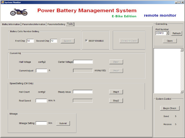
Name |
description |
range [unit] |
remarks |
|
First Chip |
sets the number of cells connected to the BMS via the first JST connector |
4-12 |
|
|
Second Chip |
sets the number of cells connected to the BMS via the second JST connector |
0 (if not used) or 4-12 |
|
|
BEEP ENABLE |
Sets beep on/off |
||
|
Current Adj |
sets the calibration factor for the current sensor |
factory set! 'config2' shows the hall sensor voltage in [mV] see 1) |
|
|
Center Voltage |
sets the offset for the current sensor |
factory set! |
|
|
Speed setting |
Function not enabled yet! |
||
|
Milage |
Function not enabled yet! |
|
cells |
chip1:chip2 |
comments |
|
24s |
12:12 |
|
|
23s |
12:11 |
|
|
22s |
12:10 |
|
|
11:11 |
||
|
21s |
12:09 |
|
|
11:10 |
||
|
20s |
12:08 |
|
|
11:09 |
||
|
10:10 |
||
|
19s |
12:07 |
|
|
11:08 |
||
|
10:09 |
||
|
18s |
12:06 |
|
|
11:07 |
||
|
10:08 |
||
|
09:09 |
||
|
17s |
12:05 |
|
|
11:06 |
||
|
10:07 |
||
|
09:08 |
||
|
16s |
12:04 |
|
|
11:05 |
||
|
10:06 |
||
|
09:07 |
||
|
08:08 |
||
|
15s |
12:03 |
|
|
11:04 |
||
|
10:05 |
||
|
09:06 |
||
|
08:07 |
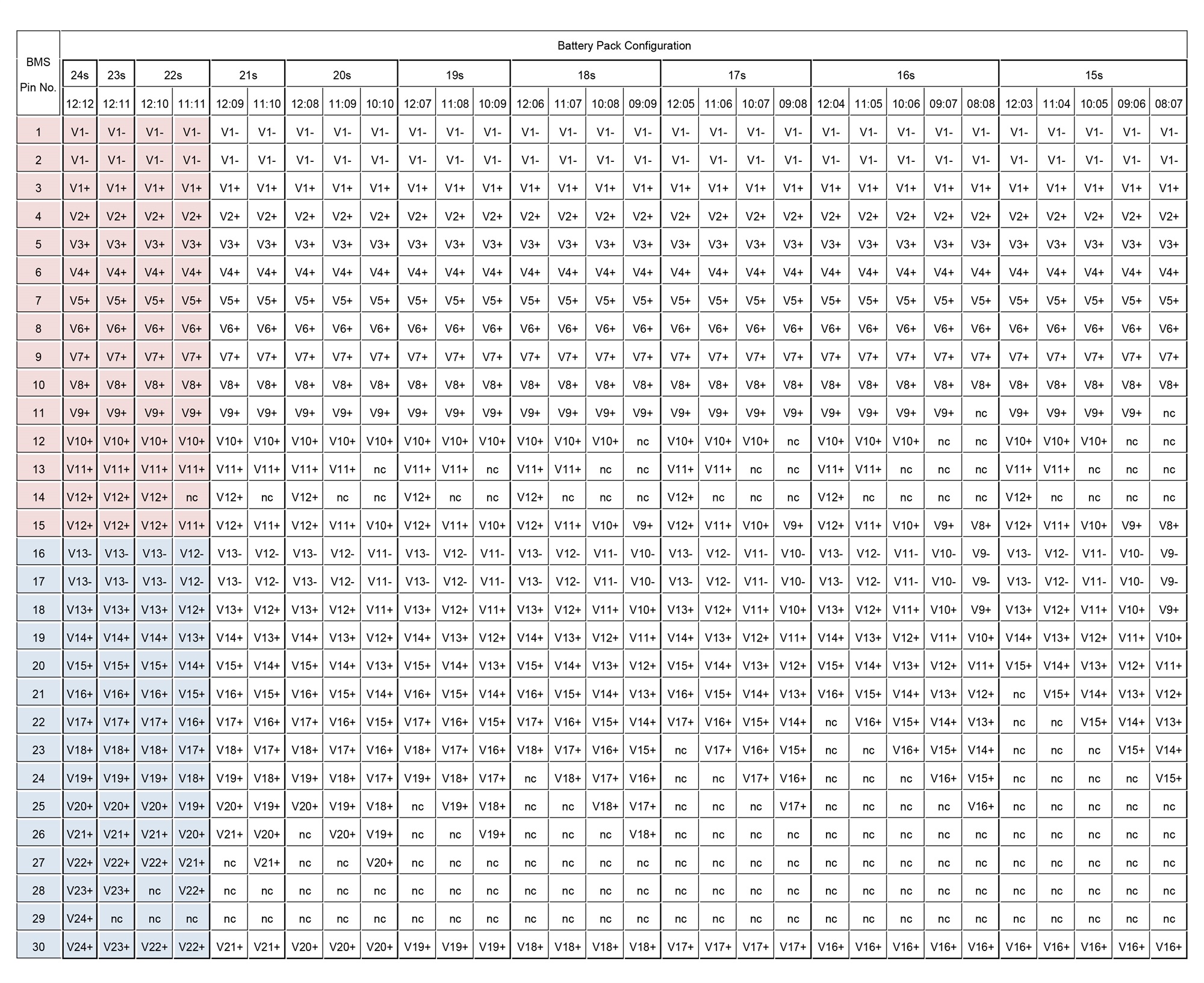
comments: nc = not connected; red text = pay attention
For 13s and 14s battery packs continue the same scheme as indicated in the table above
For 4s to 12s battery packs use only first chip following the same scheme as indicated in the table above
Edit by editor
Last Update:2022-12-27 16:53:06
All Rights reserved © 2026 Evlithium Limited