 |
Welcome To Evlithium Best Store For Lithium Iron Phosphate (LiFePO4) Battery |
 |
Individual pricing for large scale projects and wholesale demands is available.
Mobile/WhatsApp/Wechat: +86 156 0637 1958
Email: info@evlithium.com
Features
|
Model |
GE-F60 |
|
System Specification |
|
|
Model |
GE-F60-V1 |
|
AC Output Frequency and Voltage |
50/60Hz; 3L/N/PE 220/380, 230/400Vac |
|
Grid Type |
Three phase |
|
Energy Configuration (kWh) |
61.4 |
|
Dimension (W x D x H,mm) |
735x1050x2250(no contain inverter) |
|
Weight Appr. (kg) |
950(battery)+80(inverter) |
|
AC Output Rated Current (A) |
75.8 |
|
Battery Operating Voltage (V) |
500 ~ 700 |
|
Max. charging/discharging efficiency |
91% |
|
Battery Chemistry |
LiFePO4 |
|
IP Rating of Enclosure |
IP55 |
|
Installation Style |
Floor-Mounted |
|
Warranty |
10 years |
|
Inverter Technical Specification |
|
|
Max. PV Input Power (W) |
65000 |
|
Max. PV Input Current (A) |
36+36+36+36 |
|
Rated PV Input Voltage (Vdc) |
600 |
|
Start Up DC Voltage (Vdc) |
180 |
|
MPPT Voltage Range (Vdc) |
150-850 |
|
Max. PV Short-circuit Current (A) |
55+55+55+55 |
|
Number of MPPT |
4 |
|
Peak Power (off grid) |
1.5 time of rated power, 10s |
|
Power Factor |
0.8 leading to 0.8 lagging |
|
THD |
<3% |
|
DC injection current (mA) |
<0.5%ln |
|
Display |
LCD |
|
Operating Temperature Range (℃) |
-40~60( >45℃ derating) |
|
Relative Humidity |
15% ~ 85% (No Condensing) |
|
Dimension (W x D x H,mm) |
527x294x894 |
|
Inverter Communication |
CAN,RS485,WIFI,ETH |
|
Max. Efficiency |
97.6% |
|
MPPT Efficiency |
99.9% |
|
Battery Technical Specification |
|
|
Battery Module Nominal Voltage (V) |
51.2 |
|
Battery Module Energy (kWh) |
5.12 |
|
BMS Communication |
CAN |
|
Battery Module Dimension(W*D*H mm) |
440x570x133 |
|
Battery Module Weight (kg) |
44 |
|
Operating Temperature Range |
Charge: 0~55℃ / Discharge: -20℃~55℃ |
|
Cycle Life |
≥6000(@25℃±2℃,0.5C/0.5C,70%EOL) |
|
Battery Module Certification |
CE, IEC62619, IEC62040, UN38.3 |
Safety EMC / Standard: IEC/EN 62109-1,IEC/EN 62109-2,IEC/EN 61000-6-1, IEC/EN 61000-6-2,IEC/EN 61000-6-3,IEC/EN 61000-6-4
Grid Regulation: VDE4105,IEC61727/62116,VDE0126,AS4777.2,CEI0 21,EN50549-1, G98, G99, C10-11, UNE217002, NBR16149/ NBR16150
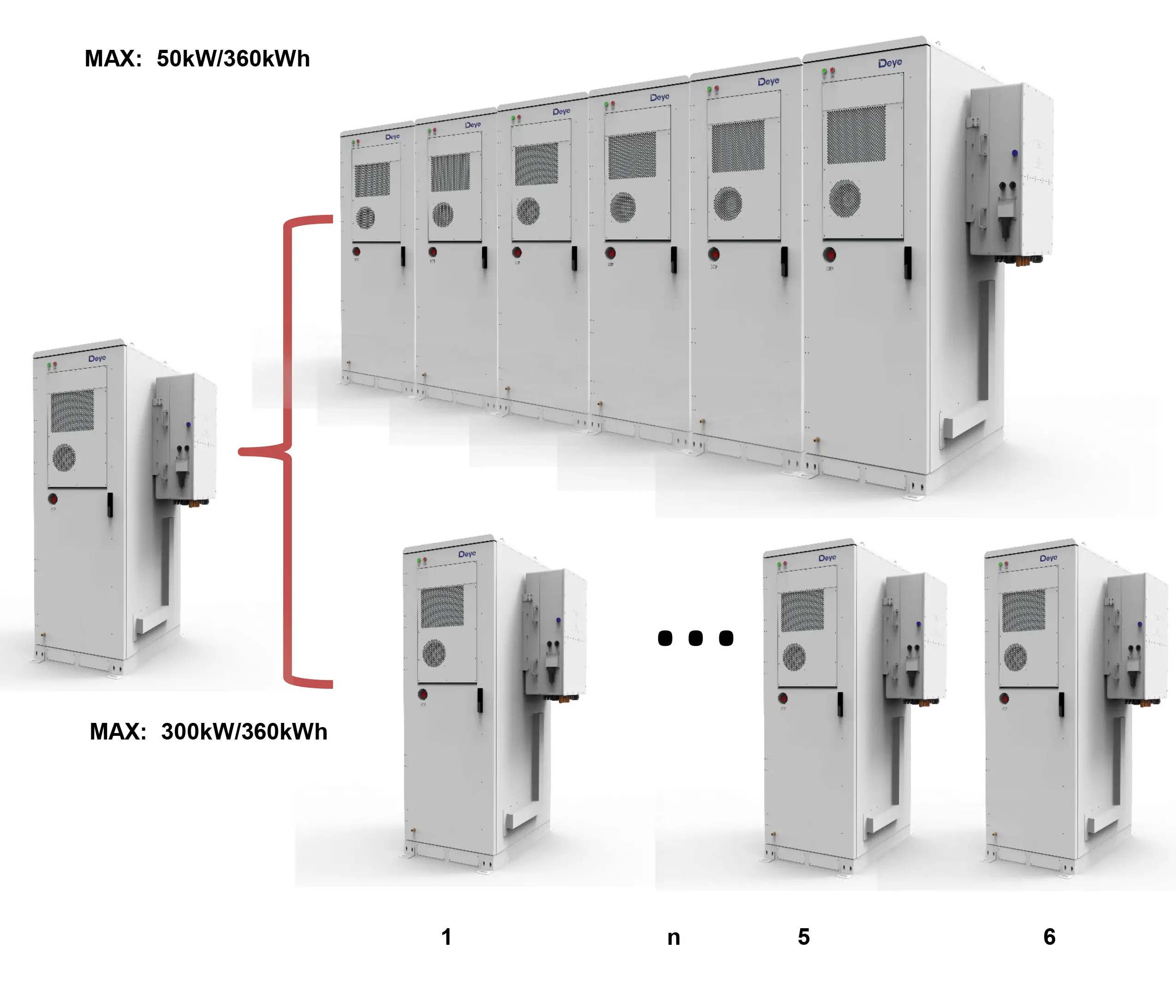
Product expansion
|
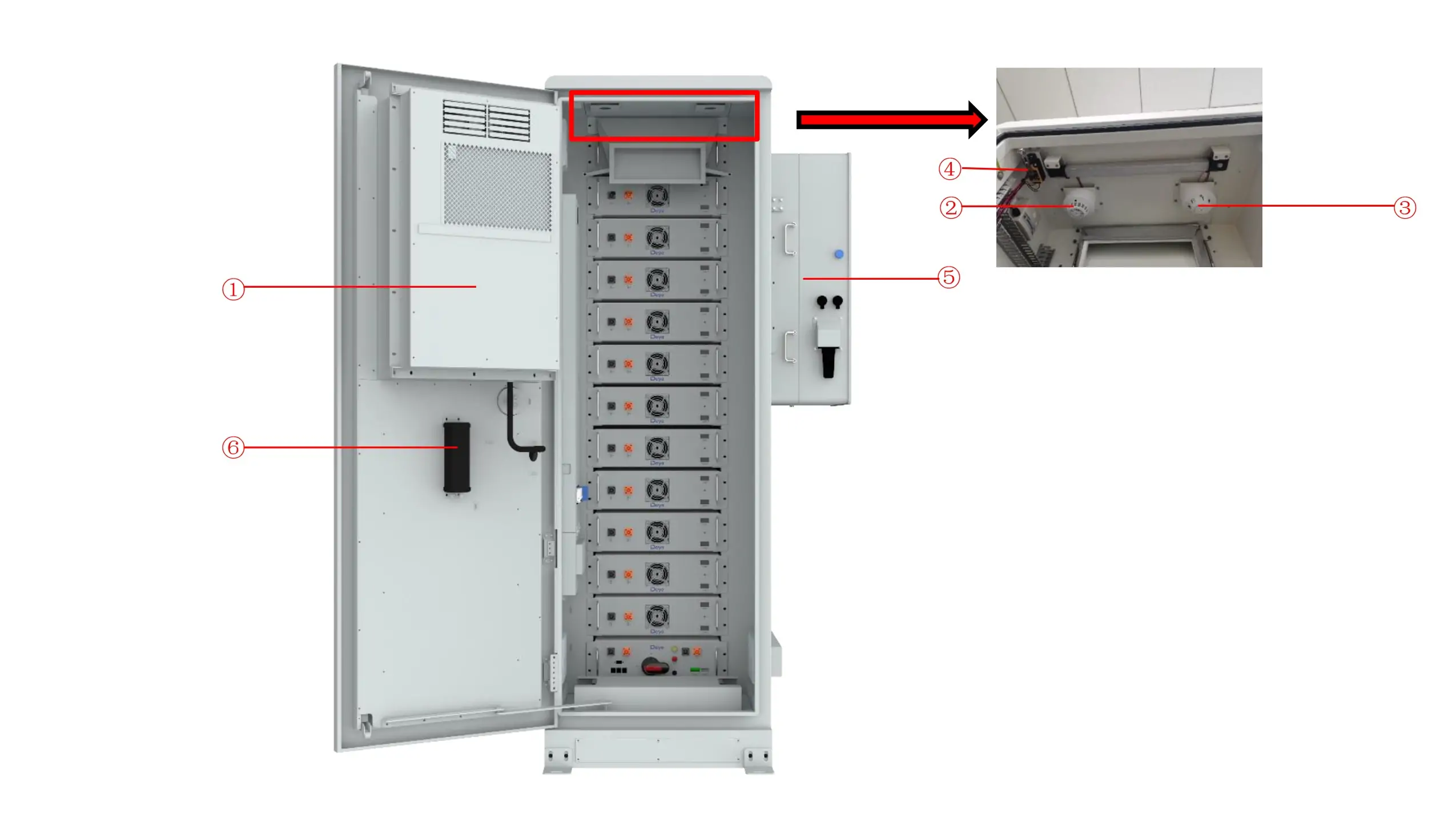
①Air conditioner |
Cooling the ESS system |
|
②Smoke detector |
A device used to detect smoke in a fire and sound an alarm when smoke is detected. |
|
③Heat detector |
A device used to measure temperature and sound an alarm if it detects excessive temperature. |
|
④Travel switch |
Check whether the ESS system door is closed. |
|
⑤Inverter |
A device that converts direct current generated by a battery into alternating current. |
|
⑥Aerosol fire extinguishing device |
When the ESS is detected to be on fire, aerosol is emitted to extinguish the fire. |
|
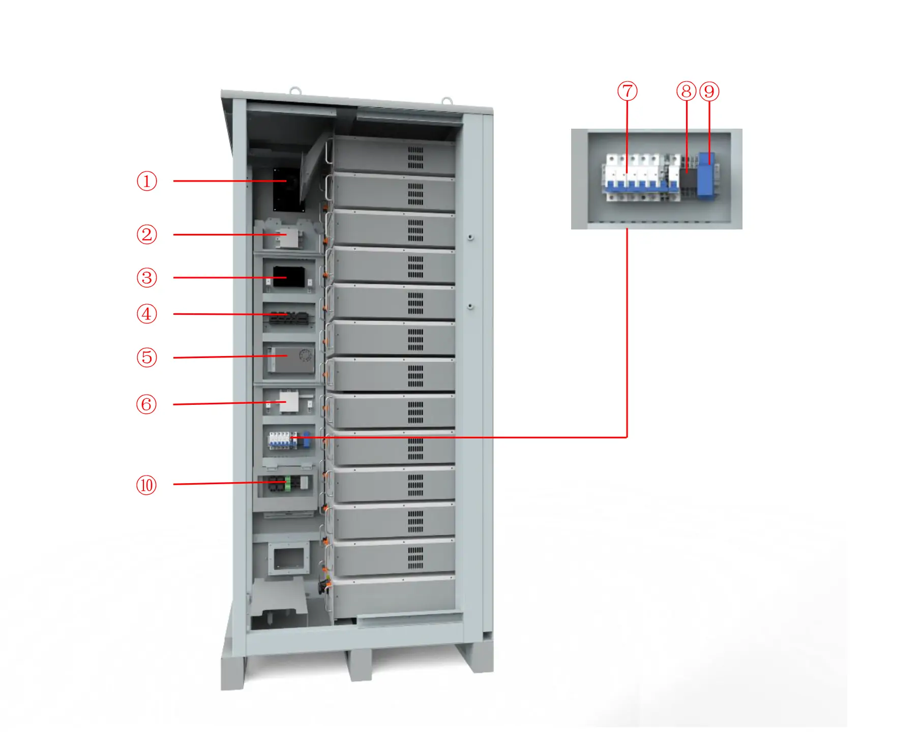
①Fan |
Emission of combustible gas |
|
②Combustible gas sensor |
Detect combustible gases |
|
③Serial relay |
Control system |
|
④Terminal line |
For connecting cables |
|
⑤Switching Mode Power Supply |
Power source |
|
⑥Temperature and humidity sensor |
Used to measure ambient temperature and humidity |
|
⑦Miniature circuit breaker |
Controlled power-on and power-off |
|
⑧Relay |
Automatic regulation, safety protection, conversion circuit |
|
⑨Water immersion sensor |
Check the ESS for water leakage |
|
⑩Terminal line |
Connect external cables |
|
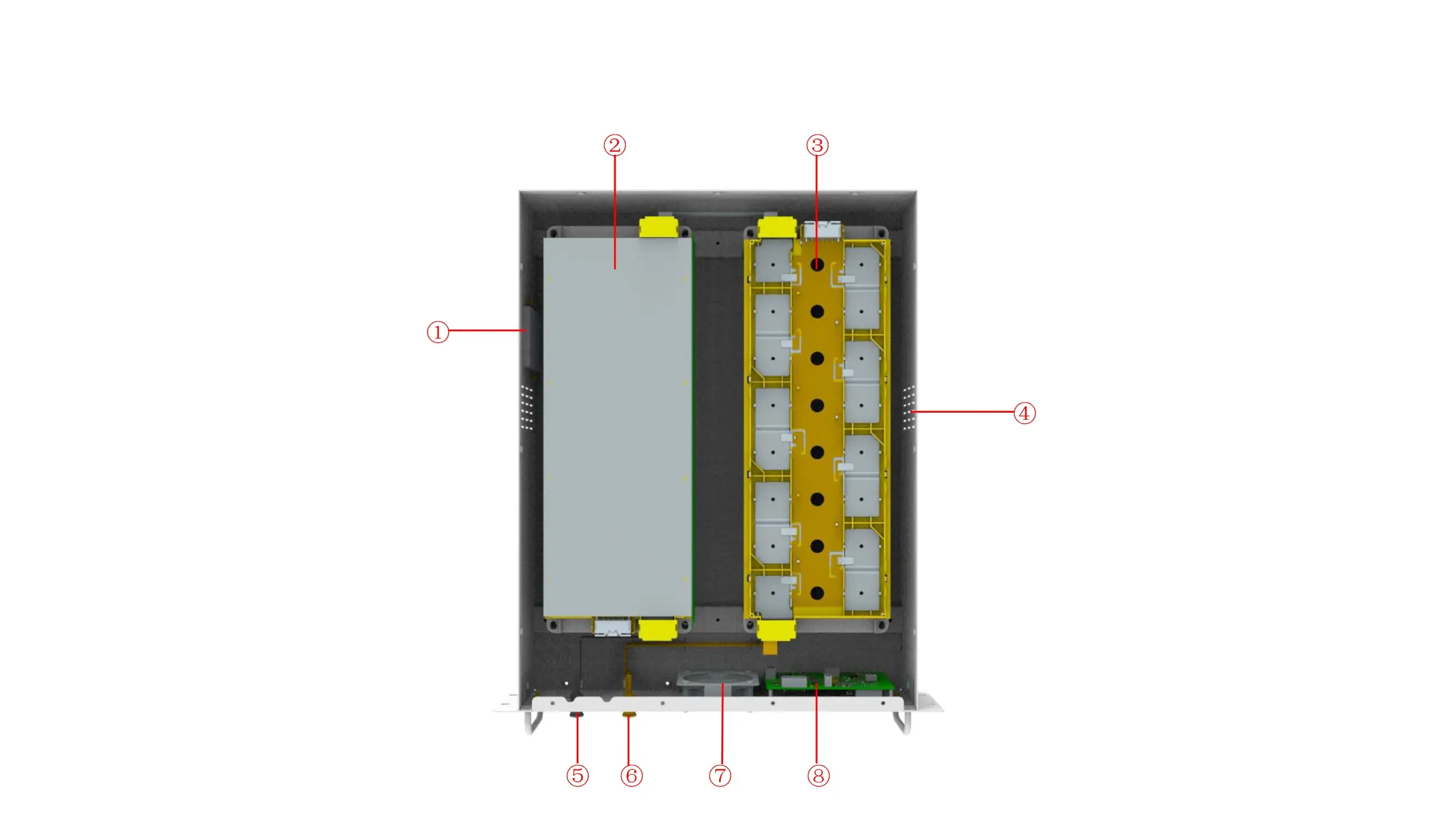
①Aerosol fire extinguishing device |
When the pack is detected to be on fire, aerosol is emitted to extinguish the fire |
|
②Battery module |
Provides electrical energy storage and output |
|
③CCS |
Cells Contact System |
|
④Air inlet |
Cold air inlet |
|
⑤Battery negative- |
/ |
|
⑥Battery positive+ |
/ |
|
⑦Fan |
Promote internal and external air flow |
|
⑧BMU |
Battery monitoring |
|
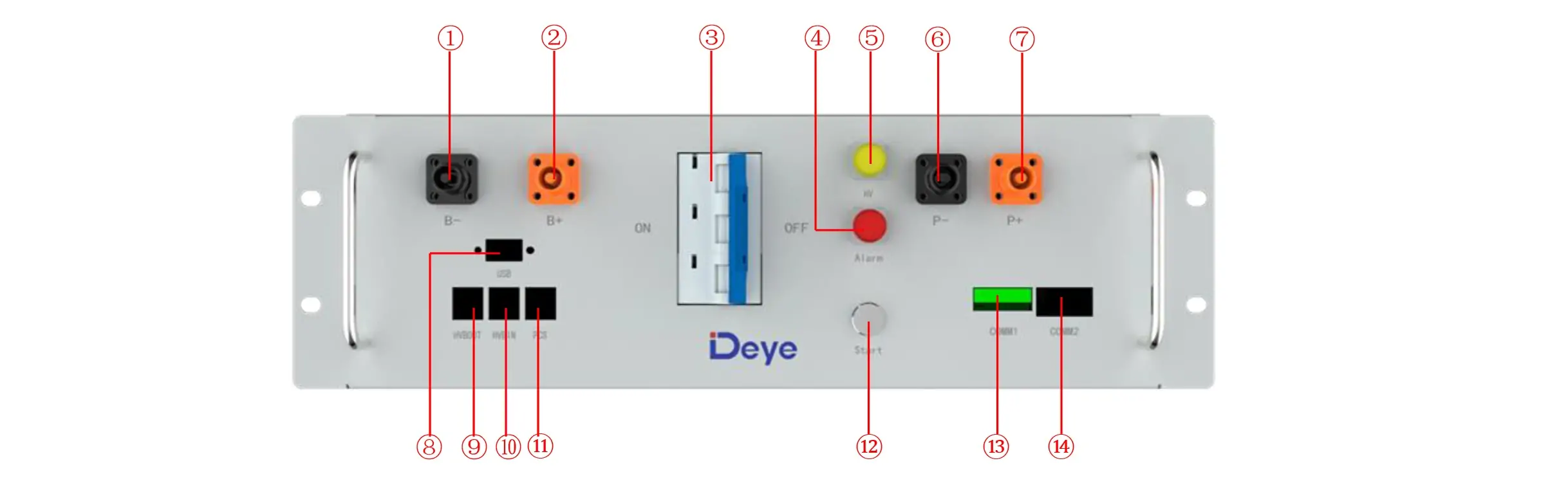
①B- |
Connection position of the common negative pole of the battery |
|
②B+ |
Connection position of the common positive pole of the battery |
|
③Air switch |
Used to manually control the connection between the battery rack and external devices |
|
④ALRM light indicator |
Battery system fault alarm indicator |
|
⑤HV light indicator |
High-voltage hazard indicator |
|
⑥PCS- |
Connection position of PCS negative pole |
|
⑦PCS+ |
Connection position of PCS positive pole |
|
⑧USB |
BMS upgrade interface and storage expansion interface |
|
⑨OUT COM |
Connection position with next HVB-100A 750V communication output |
|
⑩IN COM |
Connection position with previous HVB-100A750V communication input |
|
⑪PCS COM |
Communication interface with charging and discharging equipment |
|
⑫START |
A start switch of 12VDC power inside the high-voltage control box |
|
⑬COMM1 |
Communicative connection with the cabinet |
|
⑭COMM2 |
Communicative connection with the first battery module; and providing 12VDC power for the first battery module. |
All Rights reserved © 2026 Evlithium Limited