 |
Welcome To Evlithium Best Store For Lithium Iron Phosphate (LiFePO4) Battery |
 |
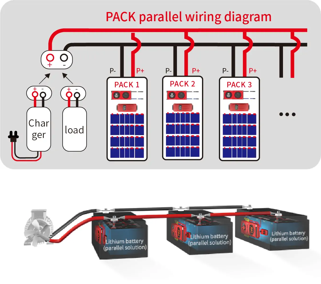
The PACK parallel BMS is a battery management system that consists of two parts: the BMS and the parallel current limiting module. Both parts must be present in each PACK that is connected in parallel.
There are two methods for wiring the PACK parallel BMS:
Method 1: This method involves connecting the parallel BMS module¡¯s P-wire to the BMS first. The common port should be connected to the BMS P-wire and the separate port should be connected to the BMS C-wire. Then connect B- and B+ in turn. After connecting the wires, plug in the BMS and parallel BMS module ports first, then the B+ port, and finally plug in the control signal wire to the protection board.
Method 2: This method involves plugging in the BMS and parallel BMS module ports first, then plugging in the B+ port, and finally plugging in the control signal wire to the BMS.
It is important to follow these methods strictly and operate in sequence. Reversing the wiring sequence can cause damage to the parallel BMS module.
The BMS and parallel BMS modules must be used together and cannot be mixed. Wiring should be done according to the purchased parallel BMS module corresponding to the current.

Edit by editor
Last Update:2023-09-25 15:51:22
All Rights reserved © 2026 Evlithium Limited