 |
Welcome To Evlithium Best Store For Lithium Iron Phosphate (LiFePO4) Battery |
 |
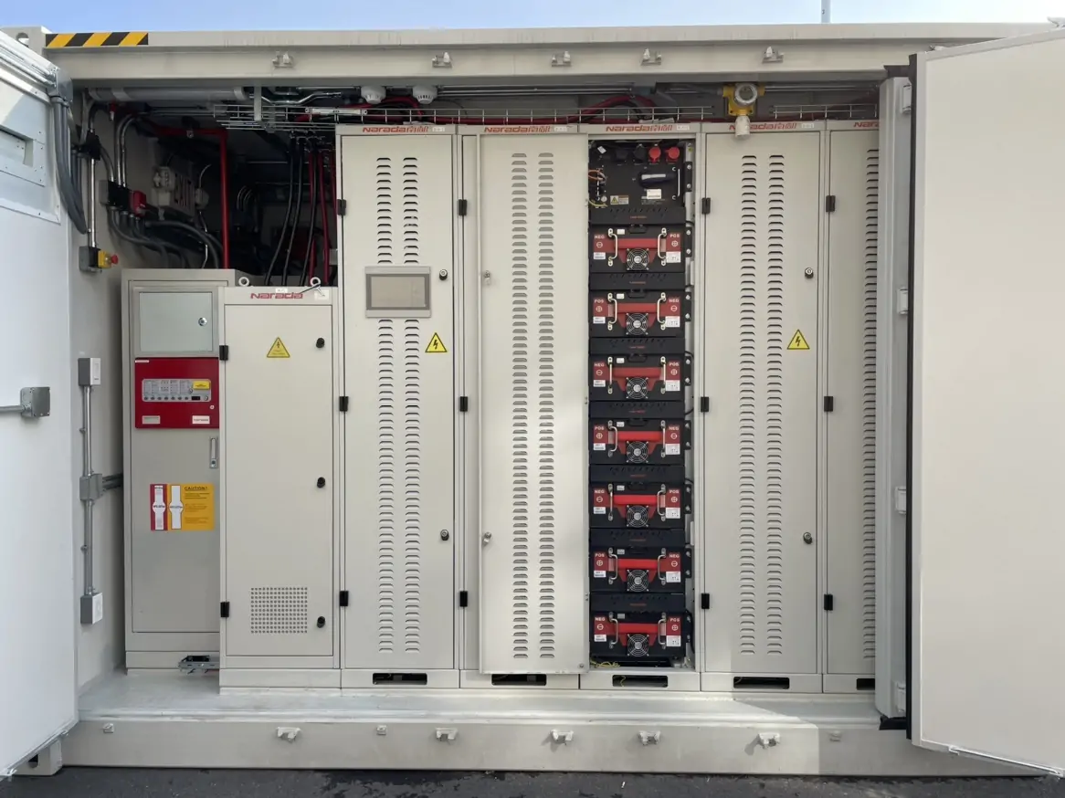
A battery energy storage system (BESS) consists of several interconnected components that work together to store electricity, manage energy flow, and maintain safe operation. Although battery cells and modules store the energy, three critical systems determine how effectively the entire installation performs: the battery management system (BMS), energy management system (EMS), and power conversion system (PCS).
Each component serves a distinct purpose. The BMS monitors battery conditions and protects cells from unsafe operating conditions. The EMS determines when and how the energy storage system should charge or discharge. The PCS converts electrical power between the battery's direct current (DC) circuit and the alternating current (AC) grid or connected loads.
Understanding the differences between BMS, EMS, and PCS is essential for engineering, procurement, and construction (EPC) contractors, system integrators, facility operators, and commercial energy storage investors. Clear functional boundaries help teams select compatible equipment, establish reliable control strategies, reduce commissioning risks, and improve long-term system performance.
The battery management system is the primary monitoring and protection layer for the battery. It collects operating data, evaluates battery conditions, and helps ensure that cells and battery modules remain within their specified electrical and thermal limits.
In a lithium-ion battery energy storage system, the BMS plays a particularly important role because cell voltage, temperature, current, and other operating parameters directly affect battery safety, performance, and service life.
A typical BMS performs several essential functions:
Cell voltage monitoring: Measures individual cell voltages to identify abnormal conditions and voltage imbalance.
Temperature monitoring: Tracks battery temperatures to detect overheating, excessive cooling, or conditions outside the permitted operating range.
Current monitoring: Measures charging and discharging current to support protection and operating-limit calculations.
Cell balancing: Reduces voltage or state-of-charge differences between cells using the balancing method supported by the battery design.
State estimation: Estimates state of charge (SoC) and state of health (SoH) using measurements and battery models.
Fault detection: Identifies conditions such as overvoltage, undervoltage, overcurrent, and overtemperature.
Protection coordination: Requests current limitation, contactor opening, or shutdown when configured safety thresholds are reached.
Communication: Reports battery status, alarms, and permitted charging or discharging limits to the PCS and higher-level controllers.
The BMS operates close to the battery and focuses on battery-specific protection and monitoring. It does not normally determine electricity purchasing schedules, optimize building demand, or decide when a facility should discharge energy to avoid peak electricity charges.
For example, if a battery becomes too hot, the BMS can reduce the permitted charging or discharging current or trigger a protective response, depending on the system design.
The energy management system is the decision-making layer of a BESS. It evaluates energy demand, electricity prices, renewable generation, grid conditions, and battery availability to determine how the system should operate.
Unlike the BMS, which concentrates on battery conditions, the EMS coordinates the battery with the wider electrical installation. Depending on the application, it may also control photovoltaic (PV) systems, generators, electric vehicle chargers, HVAC equipment, and other flexible loads.
1. Solar self-consumption optimization
The EMS can schedule battery charging when solar generation exceeds facility demand and discharge the battery when solar production declines. This strategy helps increase the use of locally generated renewable electricity.
2. Peak shaving and demand management
Commercial and industrial facilities may face electricity demand charges based on their maximum grid demand during defined measurement intervals. The EMS can discharge the BESS when demand approaches a configured threshold, subject to battery and PCS limits.
3. Time-of-use energy arbitrage
Where electricity tariffs and market rules permit, the EMS can charge the battery during lower-cost periods and discharge it during higher-cost periods.
4. Backup energy reserve
The EMS can maintain a specified minimum SoC to preserve energy for critical loads or a planned outage strategy. Actual backup capability also depends on the PCS, switchgear, protection settings, and site electrical architecture.
5. Grid export limitation
Some installations must restrict electricity exported to the utility grid. Using appropriate meter feedback and control interfaces, the EMS can adjust battery operation to help maintain the required export limit.
6. Multi-asset coordination
Advanced EMS platforms can coordinate multiple batteries, PV inverters, generators, and controllable loads to meet site-level objectives while respecting equipment constraints.
An EMS may request a particular charging or discharging power level, but it must respect the operating limits reported by the BMS.
For instance, an EMS may request a 300 kW discharge to reduce peak demand. If battery temperature, SoC, or current limits restrict available discharge power to 220 kW, the system must operate within that lower limit.
This separation between energy optimization and battery protection is fundamental to reliable BESS design. An intelligent dispatch algorithm cannot replace dedicated battery protection functions.
The power conversion system is the bidirectional electrical interface between the battery's DC circuit and the AC electrical system.
During charging, the PCS converts AC electricity into DC power suitable for charging the battery. During discharging, it converts battery DC power into AC electricity for the facility, microgrid, or utility grid.
The PCS is therefore essential for transferring energy between the battery and the electrical network.
Depending on its configuration and specifications, a PCS may provide:
Bidirectional power conversion: Supports both battery charging and discharging.
Active power control: Regulates real-power flow according to system commands.
Reactive power control: Provides reactive-power management when supported by the equipment and permitted by the interconnection requirements.
Current and DC-link regulation: Maintains controlled electrical operation during power conversion.
Grid synchronization: Coordinates converter operation with grid voltage and frequency in grid-connected applications.
Anti-islanding protection: Supports the required protection strategy for applicable grid-connected installations.
Power ramp-rate control: Limits how quickly charging or discharging power changes.
Operating-mode control: Supports grid-connected or islanded operation when the PCS and overall system are specifically designed for those modes.
Not every PCS supports grid-forming operation, black start, or seamless transition to islanded operation. These capabilities require explicit equipment support and appropriate system-level engineering.
One important distinction in BESS engineering is the difference between power and energy.
PCS power rating: Usually expressed in kilowatts (kW) or megawatts (MW), indicating how quickly the system can transfer electricity.
Battery energy capacity: Usually expressed in kilowatt-hours (kWh) or megawatt-hours (MWh), indicating how much energy the battery can store.
For example, a system rated at 1 MW/2 MWh has a nominal two-hour energy-to-power ratio when operating at its rated power. Actual discharge duration depends on usable capacity, operating limits, conversion losses, auxiliary consumption, and other design factors.
The PCS establishes the available AC conversion capability, but actual output also depends on battery discharge limits, thermal conditions, and grid interconnection constraints.
Although these systems work together, their responsibilities differ significantly.
| Comparison | BMS | EMS | PCS |
|---|---|---|---|
| Primary role | Battery monitoring and protection | Energy optimization and dispatch | Electrical power conversion |
| Main focus | Cell and module conditions | Site energy demand and operating strategy | DC-to-AC and AC-to-DC conversion |
| Typical inputs | Voltage, current, temperature, cell status | Meter readings, tariffs, PV output, SoC, operating schedules | Power commands, electrical measurements, protection signals |
| Typical outputs | Alarms, operating limits, battery status | Charging and discharging targets | Controlled electrical power |
| Key objective | Maintain safe battery operation | Meet energy and economic objectives | Deliver power within equipment limits |
| Typical ratings | Battery-specific parameters | Site-level energy and control parameters | kW or MW |
| Typical applications | Battery protection and diagnostics | Peak shaving, self-consumption, energy arbitrage | Charging and discharging the battery |
The BMS protects the battery, the EMS determines the operating strategy, and the PCS executes electrical power conversion. Together, these components form a coordinated control architecture rather than three interchangeable products.
Consider a commercial warehouse equipped with rooftop solar panels, a battery energy storage system, and a demand-charge reduction strategy.
During the afternoon, facility electricity consumption rises and grid demand approaches the site's configured limit.
The EMS detects the increasing demand through site meters and requests a 300 kW battery discharge. The PCS receives the command and prepares to convert battery DC power into AC power for the warehouse.
At the same time, the BMS continuously monitors battery voltage, temperature, SoC, and current. If it determines that the battery can safely supply only 220 kW, the control system must respect that restriction. The PCS cannot deliver the requested 300 kW if the battery or another system constraint prevents it.
The result is a coordinated sequence:
The EMS identifies an energy management requirement.
The EMS sends a charging or discharging target.
The PCS regulates electrical power according to the command and its operating limits.
The BMS continuously evaluates battery conditions and communicates permitted operating limits.
The EMS adjusts its strategy based on actual power delivery, battery availability, and site conditions.
During charging, the process works in the opposite direction. The EMS requests charging power, the PCS converts AC power into DC power, and the BMS limits charging current when necessary to keep the battery within its specified operating range.
Importantly, safety-related restrictions must not depend solely on the EMS. The BMS and PCS require appropriate protection and interlock arrangements so that abnormal conditions can trigger the necessary response even if higher-level communications fail.
Unclear control interfaces can create commissioning delays, unexpected performance limitations, and disputes over equipment responsibilities. EPC contractors and system integrators should define the responsibilities of the BMS, EMS, and PCS before selecting equipment.
Key procurement considerations include:
Control hierarchy: Identify the master controller, subordinate devices, command authority, and priority rules for normal operation, faults, and emergency shutdowns.
Communication protocols: Specify supported protocols, such as Modbus TCP, Modbus RTU, or other required interfaces, along with data points, update rates, timeouts, and communication-loss behavior.
Battery data access: Confirm that the EMS receives the necessary SoC, SoH, temperature, alarm, availability, and charge/discharge-limit information.
PCS performance: Define continuous power ratings, short-duration overload capability, efficiency, reactive-power requirements, power factor, and applicable grid-code functions.
Operating limits: Establish minimum and maximum SoC, reserve capacity, charging and discharging limits, and operating restrictions under abnormal temperatures.
Response times: Set measurable requirements for peak shaving, export limitation, power ramping, and backup transition where applicable.
Cybersecurity and access control: Define remote access permissions, authentication, event logging, network segmentation, and responsibilities for software updates.
Commissioning and acceptance tests: Include meter polarity verification, current transformer (CT) placement checks, dispatch accuracy tests, alarm validation, communication-failure simulations, and power response measurements.
The tender should also define warranty responsibilities, performance guarantees, maintenance obligations, and the division of responsibility between equipment suppliers and the system integrator.
Even a well-designed EMS cannot optimize a BESS if its measurements are inaccurate or delayed. Meter location, CT orientation, sensor calibration, timestamp synchronization, and network reliability all affect control performance.
For example, an incorrectly installed CT may cause the EMS to misinterpret whether the facility is importing or exporting electricity. The controller may then issue an inappropriate battery command, reducing peak-shaving effectiveness or compromising export-limit control.
Operators also need clear diagnostic information when the system fails to meet a power target. Possible causes include a BMS-imposed current limit, a PCS power restriction, unavailable battery capacity, communication failure, or an unexpected change in site demand.
A well-integrated monitoring platform should record commands, actual power, operating limits, alarms, and event timestamps. This information helps maintenance teams identify the root cause of performance issues and verify compliance with contractual requirements.
The BMS, EMS, and PCS perform different but complementary functions in a battery energy storage system. The BMS monitors battery conditions and enforces operating limits. The EMS coordinates energy flows according to site requirements and economic objectives. The PCS converts electrical power between the battery and the AC system.
For EPC contractors, project developers, and commercial energy storage users, understanding these distinctions is essential when evaluating BESS proposals and planning system integration.
A reliable project requires more than selecting a battery with sufficient capacity or a PCS with an appropriate power rating. It also requires a clearly defined control hierarchy, compatible communication interfaces, coordinated protection functions, accurate monitoring, and verified commissioning procedures.
When these elements work together, a BESS can deliver more predictable performance, improve energy utilization, and support safe, efficient operation throughout its service life.
No. The BMS monitors battery conditions, estimates battery status, balances cells, and enforces battery operating limits. The EMS manages system-level energy strategies, including peak shaving, solar self-consumption, backup reserves, and electricity tariff optimization.
Not exactly. A PCS is a power conversion system designed to manage power flow between the battery's DC side and the AC electrical system. It typically performs inverter and rectifier functions. However, supported operating modes and grid functions vary by product, so the technical datasheet should define the exact capabilities.
The PCS determines the system's AC power conversion capability, subject to battery current limits, thermal conditions, and site interconnection restrictions. The battery's usable energy capacity determines how long the system can sustain a given output.
No. The EMS must respect the battery's permitted operating range. If the BMS restricts charging or discharging because of temperature, voltage, SoC, or another operating condition, the system must follow the applicable limit.
EPC contractors should request a single-line electrical diagram, system architecture, control hierarchy, interface matrix, BMS/EMS/PCS communication specifications, power and energy ratings, operating limits, response-time requirements, alarm lists, commissioning procedures, cybersecurity requirements, warranty terms, and clearly assigned supplier responsibilities.
Yes, if the complete system is designed and configured for backup or islanded operation. The PCS must support the required operating mode, and the installation must include compatible switchgear, protection coordination, control logic, and load arrangements. Grid-forming capability and black-start functionality should be confirmed explicitly rather than assumed from the presence of a bidirectional PCS.
Edit by paco
Last Update:2026-10-26 11:00:52
All Rights reserved © 2026 Evlithium Limited