| Welcome To Evlithium Best Store For Lithium Iron Phosphate (LiFePO4) Battery |
 |
Individual pricing for large scale projects and wholesale demands is available.
Mobile/WhatsApp/Wechat: +86 156 0637 1958
Email: info@evlithium.com
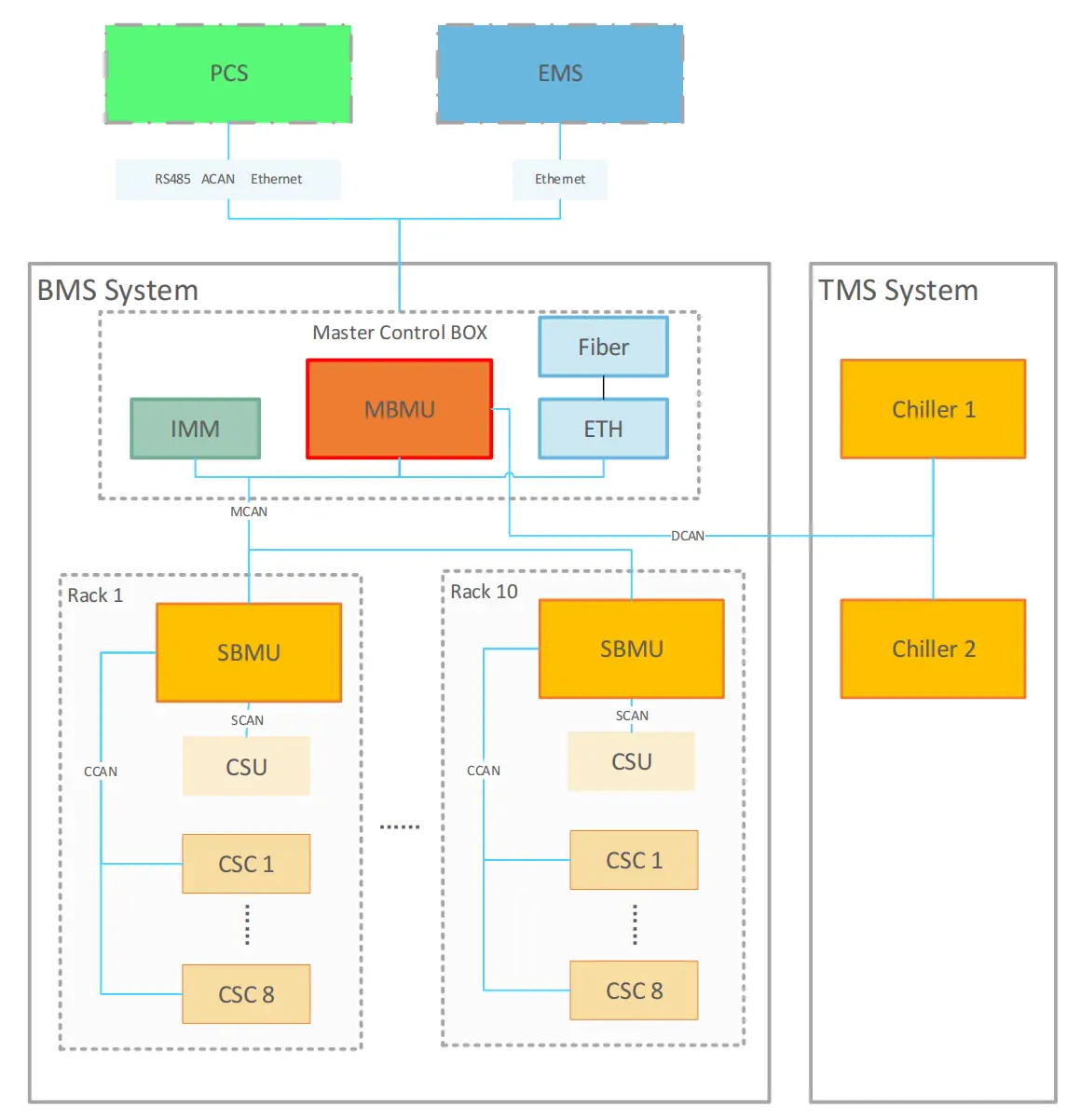
EnerC liquid-cooled energy storage battery containerized energy storage system is an integrated high energy density system, which is in consisting of battery rack system, battery management system (BMS), fire suppression system (FSS), thermal management system (TMS) and auxiliary distribution system.
Battery Racks, BMS, TMS, FSS, and Auxiliary distribution system
The battery system is composed of 10 battery racks in parallel. 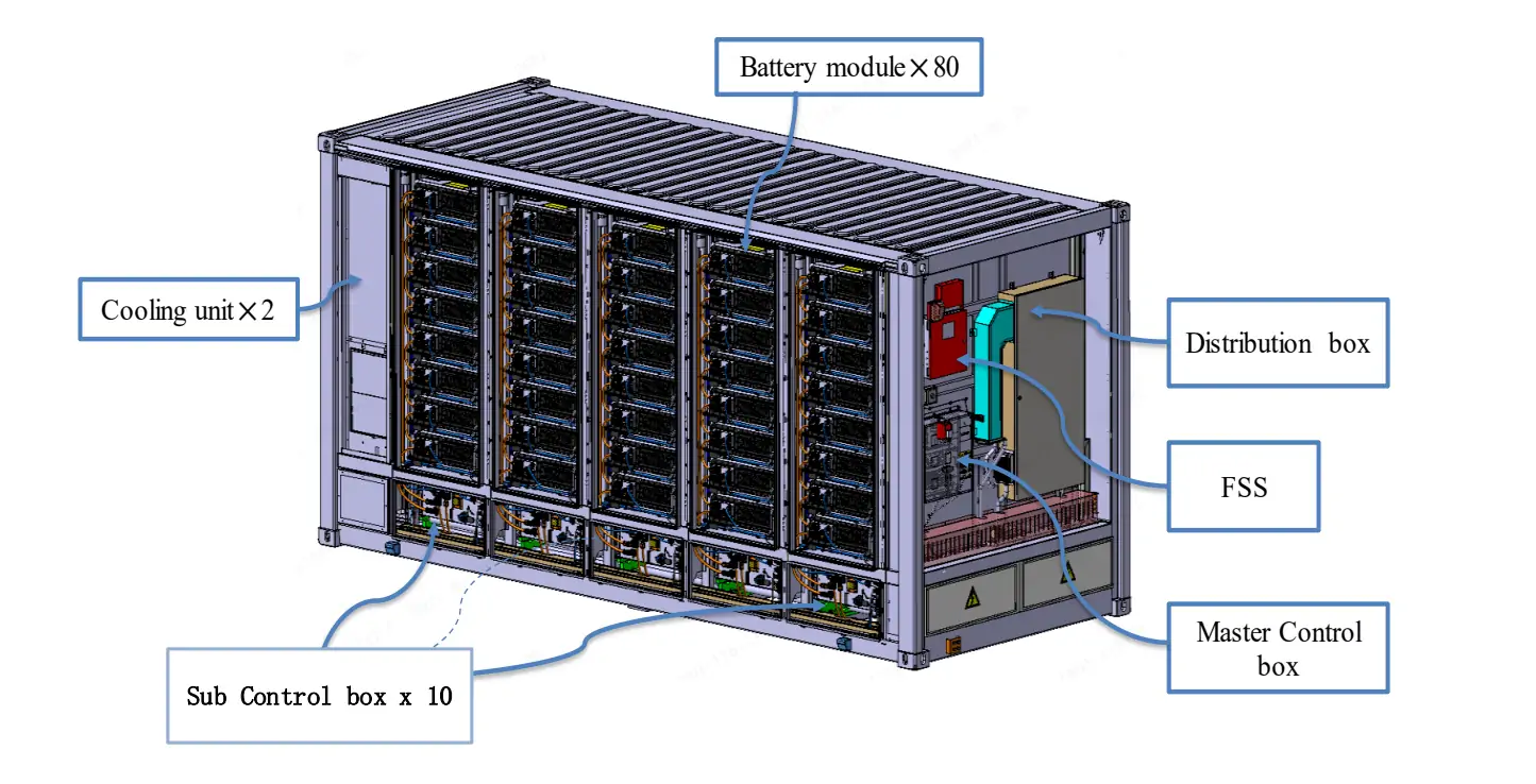 The battery system is composed of 10 battery racks in parallel. Each battery rack contains 8 battery modules by series connection, each battery module is composed of 52 battery cells in series connection also, so each rack contains 416 battery cells. Totally, EnerC liquid-cooled container’s configuration is 10P416S.
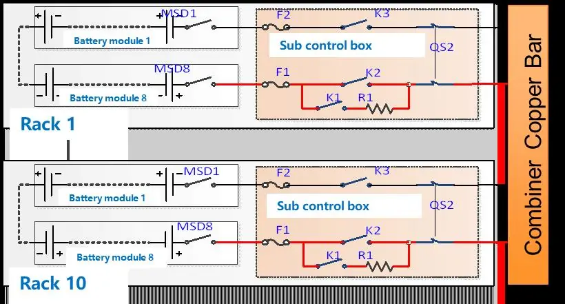
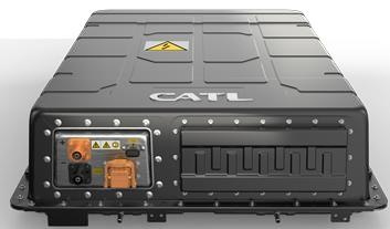
Total 52 pieces lithium iron cells (280Ah/3.2V) in series connection are used for every battery module. For safety protection, an internal high speed DC fuse is included, and removable MSD switch can cut off the high voltage connection during transportation process.
|
Item |
Specification |
|
|
Configuration |
10P416S |
|
|
Rated Energy |
3727.36kWh |
|
|
Rated Voltage |
1331.2VDC |
|
|
Voltage Range |
1164.8~1497.6VDC |
|
|
Charging Current (0.5 P) |
Rated |
1400A |
|
Maximum |
1600A |
|
|
Charging Power (0.5P) |
Rated |
1863.68kW |
|
Discharging Current (0.5P) |
Rated |
1400A |
|
Maximum |
1600A |
|
|
Discharging Power (0.5P) |
Rated |
1863.68kW |
|
Auxiliary power supply (0.5P) |
Voltage range |
3AC 380…480V |
|
Power |
Max. 36.0 kW (Including BMS & Chiller consumption) |
|
|
Operating Ambient Temperature |
Charge |
-25 ℃ to +55 ℃ |
|
Discharge |
-25 ℃ to +55 ℃ |
|
|
Environment condition |
Storage Temperature |
-30℃ to +60 ℃ |
|
Application altitude |
≤2000m |
|
|
General Parameters |
Size |
2896mm(H)*2462mm(W)*6058mm(D) |
|
Color |
RAL7042 |
|
|
Weight |
~35t |
|
|
IP Level |
IP55 (Battery Room) IPX5 (Electrical Room) IPX6(Cooling unit) |
|
|
Cooling mode |
Liquid Cooling |
|
|
Communication protocol |
CAN, TCP/IP |
|
|
Communication port |
RS485, Fiber ST |
|
|
Power connection |
Cable lug: External: 6 x M12 single hole or double hole / phase Internal: 10 x M8 single hole or double hole / phase |
|
|
Communication connection |
Fast plug |
|
|
Aux Power connection |
Terminal |
|
|
Coolant |
50% Ethylene glycol aqueous solution |
|
|
Fulfill standard |
Cell |
UN38.3 |
|
UL1973 |
||
|
GB36276 |
||
|
IEC62619 |
||
|
UL9540A |
||
|
Container |
IEC62477 |
|
|
IEC62619 |
||
|
IEC 62933-5-2 |
||
|
IEC63056 |
||
|
UL1973 |
||
|
UL9540A |
||
|
IEC 61000-4/ IEC 61000-6 |
||
All Rights reserved © 2026 Evlithium Limited