| Welcome To Evlithium Best Store For Lithium Iron Phosphate (LiFePO4) Battery |
 |
Individual pricing for large scale projects and wholesale demands is available.
Mobile/WhatsApp/Wechat: +86 156 0637 1958
Email: info@evlithium.com
Here is the Charger designed for LiFePO4 Battery Pack.
the power of the charger is 1.8kw
There are different modules of the charger
48V25A LiFePO4 Charger
72V25A LiFePO4 Charger
96V16A LiFePO4 Charger
Weight of the Charger is only 1.8kg. its one of best Charger for your LiFePO4 Battery Pack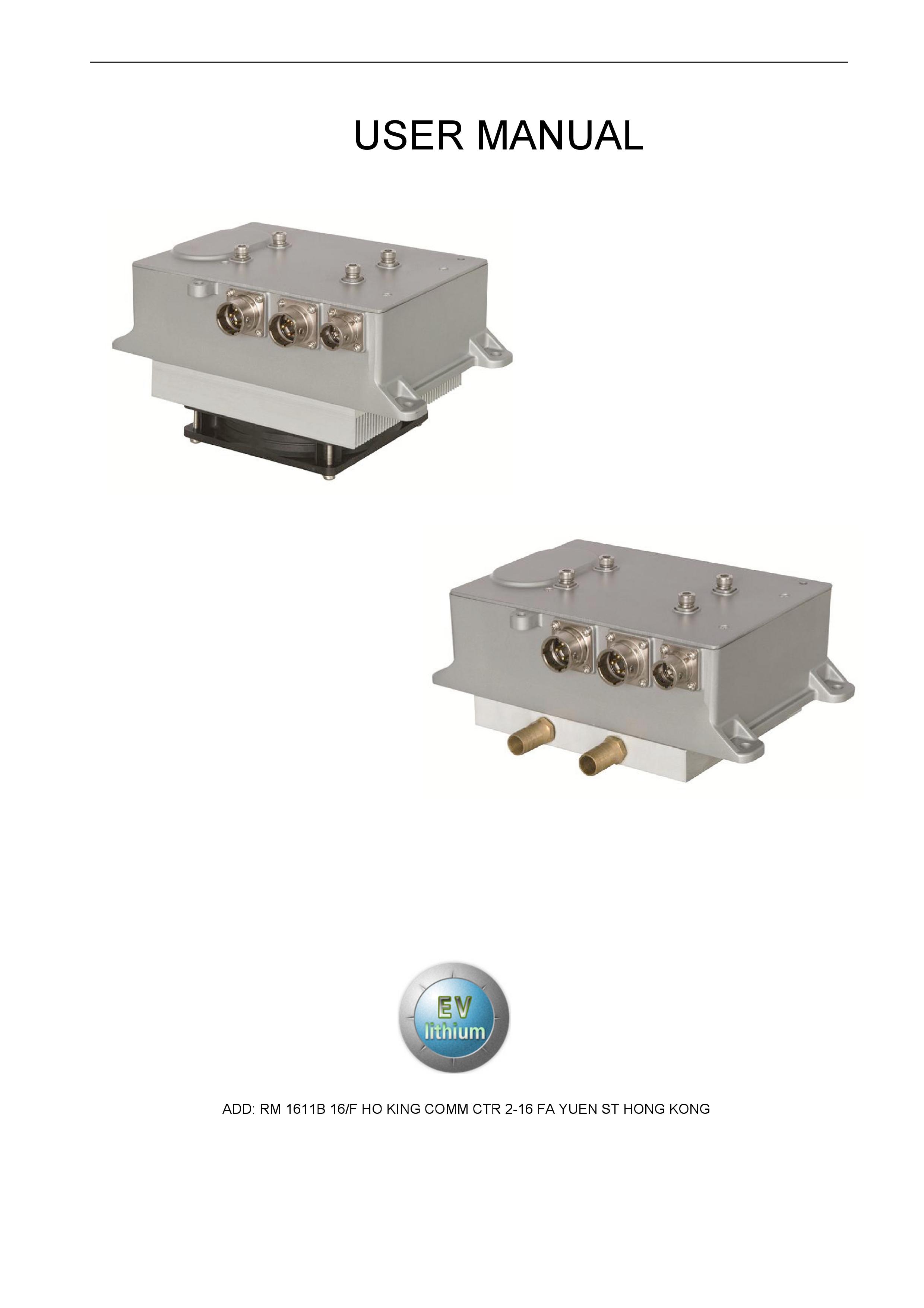
1. Overview
HK-H series 1.8KW charger was specially designed for supplying the electricity for electric vehicle’s power battery, on the basis of the national standards
for the charger. This product has the advantages of not only only high efficiency, small size, high stability, long lifespan, but also high protection grade,
and high reliability and complete protection function, etc. It’s definitely an ideal charging power supply for f electric vehicles.
This charger has built-in heat-sensing device and can automatic recover through the thermal protection. Fully sealed potting process and up to IP67
protection level ensures no causing trouble in any complex environment.
1.Key Feature:
|
|
|
|
|
|
|
|
|
|
|
Fully sealed potting process, |
|
Work reliably under -35℃- +85℃ |
|
|||||
|
water cooling ( modular optional) |
|
|
||||||
|
|
|
|
|
|
|
|||
|
Built in thermal sensor |
|
Cut off output under dangerous operations conditions |
||||||
|
|
(internal 95℃) |
|
|
|||||
|
|
|
|
|
|
|
|||
|
Protection level IP67 |
|
Work |
safely in the short-term immersion conditions |
|||||
|
2. Essential Parameter |
|
|
|
|
|
|
||
|
|
|
|
|
|
|
|
|
|
|
|
Input |
|
Output |
|
Max Output |
|
Full-load |
|
|
Hardware |
|
Voltage |
|
Power Factor |
||||
|
Current |
|
|
Current |
Efficiency |
||||
|
|
|
Range |
|
|
||||
|
|
|
|
|
|
|
|
||
|
|
|
|
|
|
|
|
|
|
|
48V25A |
9A |
|
18-68VDC |
|
25A |
≥0.99 |
≥93% |
|
|
|
|
|
|
|
|
|
(half-load more) |
|
|
|
|
|
|
|
|
|
|
|
|
72V25A |
9A |
|
25-99VDC |
|
25A |
≥0.99 |
≥93% |
|
|
|
|
|
|
|
|
|
(half-load more) |
|
|
|
|
|
|
|
|
|
|
|
|
|
|
|
|
|
|
|
|
|
|
96V16A |
9A |
|
34-132VDC |
|
16A |
≥0.99 |
≥93% |
|
|
|
|
|
|
|
|
|
(half-load more) |
|
|
|
|
|
|
|
|
|
|
|
|
|
|
|
|
|
|
|
|
|
3. Features
|
Input |
|
Frequency |
|
|
|
|
45-65Hz |
|
|
|
|
|
|
|
|
|
|
|
|
|
Stand-by Consumption |
|
|
≤5W |
||||
|
|
|
|
|
|||||
|
|
|
|
|
|
|
|
||
|
|
|
Output Mode |
|
|
|
CV / CC |
||
|
|
|
|
|
|
|
|
||
|
|
|
Output Power |
|
|
|
|||
|
Main Output |
|
|
|
|
|
|
||
|
|
CV Accuracy |
|
|
±1% |
||||
|
|
|
|
|
|
|
|
||
|
|
|
CC Accuracy |
|
|
±2% |
|||
|
|
|
|
|
|
|
|||
|
|
|
Ripple Voltage Coefficient |
|
5% |
||||
|
|
|
|
|
|
|
|||
|
Communication |
|
CAN Communication |
|
|
Yes |
|||
|
|
|
|
|
|
|
|
|
|
|
|
Baud Rate |
|
|
|
|
125Kbps、250Kbps、500Kbps |
||
|
Function |
|
|
|
|
|
|||
|
|
|
|
|
|
|
|
|
|
|
|
|
Terminal Resistance |
|
|
|
N/A |
||
|
|
|
|
|
|
|
|
|
|
|
|
12V Output |
|
|
|
|
Load Capacity of 200 mA, Output controllable |
||
|
12V5A (Optional Output Function) |
|
|
|
|
|
|||
|
|
|
|
|
|
|
|
||
|
|
|
Output Mode |
|
|
|
Constant Voltage |
||
|
|
|
|
|
|
|
|
||
|
|
|
Output Voltage |
|
|
|
13.8V |
||
|
|
|
|
|
|
|
|
||
|
|
|
Rated Current |
|
|
|
5A |
||
|
Low Voltage |
|
|
|
|
|
|
|
|
|
|
CV Accuracy |
|
|
|
±2% |
|||
|
Output |
|
|
|
|
||||
|
|
|
|
|
|
|
|
|
|
|
|
|
Maximum Current |
|
5.5A±0.5A |
||||
|
|
|
|
|
|
|
|
||
|
|
|
Output Power |
|
|
|
≥62.5W |
||
|
|
|
|
|
|
||||
|
|
|
Ripple Voltage Coefficient |
|
1% |
||||
4.Protection function
|
Input Over-voltage Protection |
|
AC270±5V |
|
Input Under-voltage Protection |
|
AC85±5V |
|
Output Over-voltage Protection |
|
Stop the output when exceeds + 1% of the maximum output voltage |
|
Output Under-voltage Protection |
|
Stop the output when below -5% of the minimum output voltage |
|
Output Over-current Protection |
|
Stop the output when exceeds + 1% of the maximum output current |
|
Over-temperature Protection |
|
Power down from 85 ℃ and turn off at 90℃ |
|
Short-circuit Protection |
|
Stop Output |
|
Battery Reverse Connect Protection |
|
Fuse Burn-out |
|
Ground Protection |
|
≤100mΩ |
|
CAN communication Protection |
|
Automatically stop the output when CAN communication fails |
|
Power-off Protection |
|
Yes |
|
5. Safety and others |
|
|
|
|
|
|
|
|
|
|
|
Input to Output:2000VAC≤10mA |
|
|
Withstand Voltage |
|
Input to Ground:2000VAC≤12mA |
|
|
|
Output to Ground:2000VAC≤10mA,all 1min |
||
|
|
|
||
|
|
|
|
|
|
Insulation Resistance |
|
Input, output, signal terminal to casing≥10MΩ |
|
|
|
Testing Voltage 1000VDC |
||
|
|
|
||
|
Electromagnetic |
|
GB/T 18487.3-2001 |
11.3.1 |
|
Immunity |
|
||
|
|
|
|
|
|
Electromagnetic |
|
GB/T 18487.3-2001 |
11.3.2 |
|
Abusive |
|
||
|
|
|
|
|
|
Harmonic Current |
|
GB 17625.1-2003 |
6.7.1.1 |
|
|
|
|
|
|
Inrush Starting Current |
|
≤24A |
|
|
|
|
|
|
|
Current-rise Time |
|
≤5S,Overshoot≤5% |
|
|
|
|
|
|
|
Close Response time |
|
100%到 10%≤50mS,100%到 0%≤200mS |
|
|
|
|
|
|
|
Protection Level |
|
IP67 |
|
|
|
|
||
|
Vibration Resistance |
10-25Hz Amplitude1.2mm,25-500Hz 30m/s2,8hrs per direction |
||
|
|
|
|
|
|
Noise |
|
≤60dB(A Level) |
|
|
|
|
|
|
|
MTBF |
|
150000H |
|
|
|
|
|
|
|
Work Environment |
|
Relative Temp 5%-95% No condensation |
|
|
|
|
|
|
|
Working Temperature |
|
-35℃ ~ +85℃ |
|
|
|
|
|
|
|
Storage Temperature |
|
-55℃ ~ +100℃ |
|
|
|
|
|
|
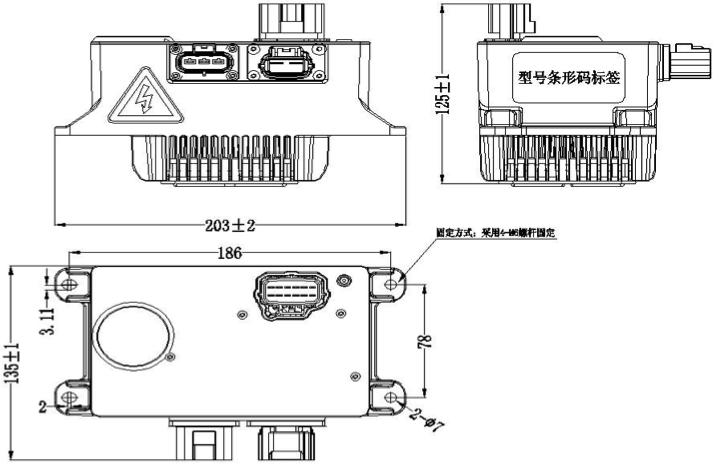
6. Installation size, label requirements and interface definitions
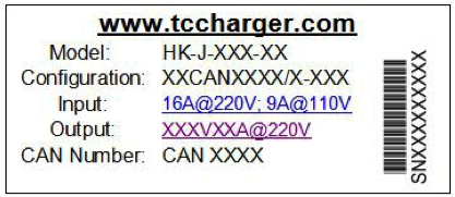
1). Installation size,Label
Label ( based on the actual situation)
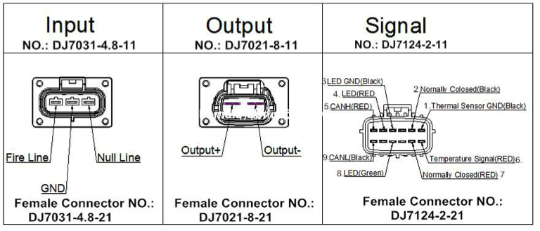
2). Interface Definitions
7. LED status
1). Initial State
Red Off Green Off Red Off Green Off Red Off Green Off Red Off Green Off
2). Charging State
Red Off Red Off Red Off Red Off Red Off Red Off Red Off Red Off
3). Stand-by State
Green Off Green Off Green Off Green Off Green Off Green Off Green Off Green Off
4). Fault State
Red Green Red Green……………Other error status word error
Red Green…………………………Wrong Battery
Red Green Red……………………Wrong Communication
Green Red…………………………Wrong Input Voltage
Green Red Green…………………Internal Temperature Protection
Green Red Green Red……………Wrong Hardware
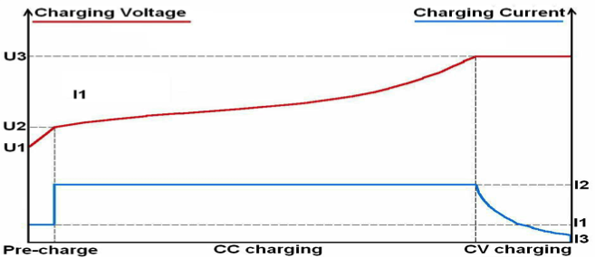
8. Charging Curve
1). CC/CV Charging mode:(for Lithium Battery)
U1= U23 ,U2= n串 ×2.5V,U3=Maximum voltage for the battery pack I1= I22 ,I2=Maximum charging current for the battery pack,I3= I62
![]()
![]() ① Pre-charge:It only enters into pre-charging process when the battery pack voltage is under U2 ( The charger does not start when battery
① Pre-charge:It only enters into pre-charging process when the battery pack voltage is under U2 ( The charger does not start when battery
pack is under U1), then it operates in a constant current charging I1, finally, the pre-charging process is completed when voltage rises to U2.
② CC Charging:It operates in a constant current charging I2, then the CC charging ends when voltage reaches to U3.
③CV Charging:Constant voltage charging with U3, the whole charging process is completed when current reduces to U3
2). Different brand-name of lead-acid batteries have different kinds of charging curves.
Below shows a typical charging curve for Chilwee battery:
9. Expansion Function

Choose the accessories according to the actual needs: 1). Thermal Sensor Interface (for lead-acid battery charger)
Thermal Sensor is recommended to lead-acid battery charger, to detect the temperature of the battery and compensate charging voltage,
2). 12V Output
Charger provides a rating voltage 12V0.2A signal output. Its electrical connections is isolated from the interior circuit of the charger for
external application function extension. Note that this 12V with LED indicator output interface are common-grounded. The independent
12V output can supply power for the battery management system. Output 12V-5A.
3). LED Output Interface
Charger provides Red, Green two LED interface or Red, Yellow, Green three LED interface. Its electrical connections is isolated from
the interior circuit of the battery charger for external application function extension.
4). ENABLE Signal (for Lithium battery charger): External control circuit must be independent circuit
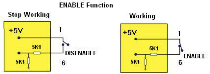
As for lithium battery charger, it’s essential to use an enable signal to control the charger’s work or close. Isolated circuit (such as Relay
or Optocoupler) shall be adopted to control the charger’s work or close. Note that if the control circuit is not independent, it lead to
damage of the charger.
5). Charging Lock up Signal(for lead acid battery)
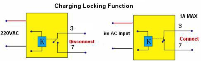
Charger provides a set of relay normally closed contact as charging locking signal output. When the charger has no electricity, the contact
connects, while the charger connects to the AC power supply, the contact disconnects immediately. The rated current of contact is 1A,
withstand voltage 30VDC / 250VAC.
10. Appearance Requirements
1). Outer surface should be smooth without obvious defects such as scratch, deformation. Surface coating should be uniform.
2). The nameplates and signs should be installed firmly with the neat handwriting.
3). Spare parts should be fastened reliably without rust, burrs, cracks and other defects and damage
4). Each product should be marked with product identification in obvious place, including part number, product brand,
product type, production number, name of production enterprises, the warning message, etc
11. Packaging, Transport and Storage
1). Packaging
On the packing box, there are product name, product part number, product brand, product type, production number and name of
manufacturer; In packing box, along with the technical documents, it includes packing list, quality certificate, product specification.
2). Transportation
Suitable for cars, boats, aircraft, transportation. The products have to be prevented against sunshine and moisture and in a civilized
transportation.
3). Storage
Product should be stored in the packing box when it is not used and be maintained in a 5 ℃ to 40 ℃ clean, dry and well-ventilated
environment. It should not be stored together with chemicals, acid and alkali substances etc,. Should avoid storing in the sun, fire,
water and avoid storing with corrosive substances. The storage period is 2 years (from the inventory date of the factory). After the
2 years of storage period, the products should still comply with the provisions of the relevant standards.
All Rights reserved © 2026 Evlithium Limited